Optical configurations
There are two basic configurations of the conventional optical microscope, the simple (one lens) and compound (many lenses). The vast majority of modern
research microscopes are compound microscopes while some cheaper commercial
digital microscopes are simple single lens microscopes. A
magnifying glass is, in essence, a basic single lens microscope. In general microscope optics are static; to focus at different focal depths the lens to sample distance is adjusted and to get a wider or narrower field of view a different magnification objective lens must be used. Most modern research microscopes also have a separate set of optics for illuminating the sample.
[edit] Single lens (simple) microscope
A
simple microscope is a microscope that uses only one lens for magnification, and is the original design of light microscope.
Van Leeuwenhoek's microscopes consisted of a small, single
converging lens mounted on a brass plate, with a screw mechanism to hold the sample or specimen to be examined.
Demonstrations by British microscopist have images from such basic instruments. Though now considered primitive, the use of a single, convex lens for viewing is still found in simple magnification devices, such as the
magnifying glass, and the
loupe.
[edit] Compound microscope
A
compound microscope is a microscope which uses multiple lenses to collect light from the sample and then a separate set of lenses to focus the light into the eye or camera. Compound microscopes are heavier, larger and more expensive than simple microscopes due to the increased number of lenses used in construction. The main advantages of multiple lenses are improved numerical aperture (see resolution limit below), reduced chromatic aberration and exchangeable objective lenses to adjust the magnification. A compound microscope also makes more advanced illumination setups, such as
phase contrast.
[edit] History
See also:
History of optics and
Timeline of microscope technology


The oldest published image known to have been made with a microscope: bees by
Francesco Stelluti, 1630
[1]
[edit] Invention
It is difficult to say who invented the compound microscope.
Dutch spectacle-makers Hans Janssen and his son
Zacharias Janssen are often said to have invented the first compound microscope in 1590, but this was a declaration made by Zacharias Janssen himself during the mid 17th century. The date is unlikely, as it has been shown that Zacharias Janssen actually was born around 1590. Another favorite for the title of 'inventor of the microscope' was
Galileo Galilei. He developed an
occhiolino or compound microscope with a convex and a concave lens in 1609. Galileo's microscope was celebrated in the
Accademia dei Lincei in 1624 and was the first such device to be given the name "microscope" a year later by fellow Lincean
Giovanni Faber. Faber coined the name from the
Greek words
μικρόν (micron) meaning "small", and
σκοπεῖν (skopein) meaning "to look at", a name meant to be analogous with "
telescope", another word coined by the Linceans.
[2]
Christiaan Huygens, another Dutchman, developed a simple 2-lens ocular system in the late 17th century that was
achromatically corrected, and therefore a huge step forward in microscope development. The Huygens ocular is still being produced to this day, but suffers from a small field size, and other minor problems.
[edit] Popularisation
Anton van Leeuwenhoek (1632–1723) is credited with bringing the microscope to the attention of biologists, even though simple magnifying lenses were already being produced in the 16th century. Van Leeuwenhoek's home-made microscopes were very small simple instruments, with a single, yet strong lens. They were awkward in use, but enabled van Leeuwenhoek to see detailed images. It took about 150 years of optical development before the compound microscope was able to provide the same quality image as van Leeuwenhoek's simple microscopes, due to difficulties in configuring multiple lenses. Still, despite widespread claims, van Leeuwenhoek is not the inventor of the microscope.
[edit] Lighting techniques
While basic microscope technology and optics have been available for over 400 years it is much more recently that techniques in sample illumination were developed to generate the high quality images seen today.
In August 1893 August Köhler developed
Köhler illumination. This method of sample illumination gives rise to extremely even lighting and overcomes many limitations of older techniques of sample illumination. Before development of Köhler illumination the image of the light source, for example a
lightbulb filament, was always visible in the image of the sample.
The
Nobel Prize in physics was awarded to Fritz Zernike in 1953 for his development of
phase contrast illumination which allows imaging of transparent samples. By using
interference rather than
absorption of light, extremely transparent samples, such as live
mammalian cells, can be imaged without having to use staining techniques. Just two years later, in 1955, George Nomarski published the theory for
differential interference contrast microscopy, another
interference-based technique for imaging transparent samples.
[edit] Fluorescence microscopy
Modern biological microscopy depends heavily on the development of
fluorescent probes for specific structures within a cell. In contrast to normal transilluminated light microscopy in
fluorescence microscopy the sample is illuminated through the objective lens with a narrow set of wavelengths of light. This light interacts with fluorophores in the sample which then emit light of a longer
wavelength. It is this emitted light which makes up the image.
Since the mid 20th century chemical fluorescent stains, such as
DAPI which binds to
DNA, have been used to label specific structures within the cell. More recent developments include
immunofluorescence, which uses fluorescently labelled
antibodies to recognise specific proteins within a sample, and fluorescent proteins like
GFP which a live cell can
express making it fluorescent.
[edit] Components
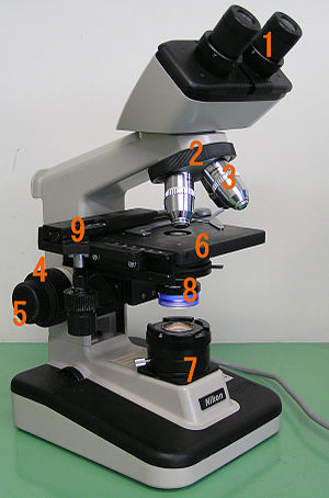
Basic optical transmission microscope elements(1990s)

Two Leica
oil immersion microscope objective lenses; left 100x, right 40x.
All modern optical microscopes designed for viewing samples by transmitted light share the same basic components of the light path, listed here in the order the light travels through them: In addition the vast majority of microscopes have the same 'structural' components:
- Ocular lens (eyepiece) (1)
- Objective turret or Revolver (to hold multiple objective lenses) (2)
-
Objective (3)
- Focus wheel to move the stage (4 - coarse adjustment, 5 - fine adjustment)
- Frame (6)
- Light source, a
light or a
mirror (7)
- Diaphragm and
condenser lens (8)
- Stage (to hold the sample) (9)
These entries are numbered according to the image on the right.
[edit] Eyepiece (ocular)
Main article:
Eyepiece
The
eyepiece, or ocular, is a cylinder containing two or more lenses; its function is to bring the image into focus for the eye. The eyepiece is inserted into the top end of the body tube. Eyepieces are interchangeable and many different eyepieces can be inserted with different degrees of magnification. Typical magnification values for eyepieces include 2×, 5× and 10×. In some high performance microscopes, the optical configuration of the objective lens and eyepiece are matched to give the best possible optical performance. This occurs most commonly with
apochromatic objectives.
[edit] Objective turret or Revolver
Objective turret or Revolver is the part that holds the set of objective lenses, it allows to change them.
[edit] Objective
For more details on this topic, see
Objective (optics).
At the lower end of a typical compound optical microscope there are one or more
objective lenses that collect light from the sample. The objective is usually in a cylinder housing containing a glass single or multi-element compound lens. Typically there will be around three objective lenses screwed into a circular nose piece which may be rotated to select the required objective lens. These arrangements are designed to be
parfocal, which means that when one changes from one lens to another on a microscope, the sample stays in
focus. Microscope objectives are characterized by two parameters, namely,
magnification and
numerical aperture. The former typically ranges from 5× to 100× while the latter ranges from 0.14 to 0.7, corresponding to
focal lengths of about 40 to 2 mm, respectively. Objective lenses with higher magnifications normally have a higher numerical aperture and a shorter
depth of field in the resulting image. Some high performance objective lenses may require matched eyepieces to deliver the best optical performance.
[edit] Oil immersion objective
Main article:
Oil immersion
Some microscopes make use of
oil-immersion objectives or water-immersion objectives for greater resolution at high magnification. These are used with
index-matching material such as
immersion oil or water and a matched cover slip between the objective lens and the sample. The refractive index of the index-matching material is higher than air allowing the objective lens to have a larger numerical aperture (greater than 1) so that the light is transmitted from the specimen to the outer face of the objective lens with minimal refraction. Numerical apertures as high as 1.6 can be achieved.
[3] The larger numerical aperture allows collection of more light making detailed observation of smaller details possible. An oil immersion lens usually has a magnification of 40 to 100×.
[edit] Focus wheels
Adjustment wheels move the stage up and down with separate adjustment for coarse and fine focussing. The same controls enable the microscope to adjust to specimens of different thickness. In older designs of microscopes, the focus adjustment wheels move the microscope tube up or down relative to the stand and had a fixed stage.
[edit] Frame
The whole of the optical assembly is traditionally attached to a rigid arm which in turn is attached to a robust U shaped foot to provide the necessary rigidity. The arm angle may be adjustable to allow the viewing angle to be adjusted.
The frame provides a mounting point for various microscope controls. Normally this will include controls for focusing, typically a large knurled wheel to adjust coarse focus, together with a smaller knurled wheel to control fine focus. Other features may be lamp controls and/or controls for adjusting the condenser.
[edit] Light source
Many sources of light can be used. At its simplest, daylight is directed via a
mirror. Most microscopes, however, have their own adjustable and controllable light source - often a
halogen lamp, although illumination using
LEDs and
lasers are becoming a more common provision.
[edit] Condenser
The
condenser is a lens designed to focus light from the illumination source onto the sample. The condenser may also include other features, such as a
diaphragm and/or filters, to manage the quality and intensity of the illumination. For illumination techniques like
dark field,
phase contrast and
differential interference contrast microscopy additional optical components must be precisely aligned in the light path.
[edit] Stage
The stage is a platform below the objective which supports the specimen being viewed. In the center of the stage is a hole through which light passes to illuminate the specimen. The stage usually has arms to hold
slides (rectangular glass plates with typical dimensions of 25 mm by 75 mm, on which the specimen is mounted).
At magnifications higher than 100x moving a slide by hand is not practical. A mechanical stage, typical of medium and higher priced microscopes, allows tiny movements of the slide via control knobs that reposition the sample/slide as desired. If a microscope did not originally have a mechanical stage it may be possible to add one.
All stages move up and down for focus. With a mechanical stage slides move on two horizontal axes for positioning the specimen to examine specimen details.
Focusing starts at lower magnification in order to center the specimen by the user on the stage. Moving to a higher magnification requires the stage to be moved higher vertically for re-focus at the higher magnification and may also require slight horizontal specimen position adjustment. Horizontal specimen position adjustments are the reason for having a mechanical stage.
Due to the difficulty in preparing specimens and mounting them on slides, for children it's best to begin with prepared slides that are centered and focus easily regardless of the focus level used.
[edit] Magnification
The actual power or
magnification of a compound optical microscope is the product of the powers of the ocular (
eyepiece) and the objective lens. The maximum normal magnifications of the occular and objective are 10× and 100× respectively giving a final magnification of 1000×.
[edit] Magnification and micrographs
When using a camera to capture a
micrograph the effective magnification of the image must take into account the size of the image. This is independent of whether it is on a print from a film negative or displayed digitally on a
computer screen.
In the case of photographic film cameras the calculation is simple; the final magnification is the product of: the objective lens magnification, the camera optics magnification and the enlargement factor of the film print relative to the negative. A typical value of the enlargement factor is around 5× (for the case of
35mm film and a 15x10 cm (6×4 inch) print).
In the case of digital cameras the size of the pixels in the
CMOS or
CCD detector and the size of the pixels on the screen have to be known. The enlargement factor from the detector to the pixels on screen can then be calculated. As with a film camera the final magnification is the product of: the objective lens magnification, the camera optics magnification and the enlargement factor.
[edit] Operation

Optical path in a typical microscope
The optical components of a modern microscope are very complex and for a microscope to work well, the whole optical path has to be very accurately set up and controlled. Despite this, the basic operating principles of a microscope are quite simple.
The objective lens is, at its simplest, a very high powered magnifying glass
i.e. a lens with a very short focal length. This is brought very close to the specimen being examined so that the light from the specimen comes to a focus about 160 mm inside the microscope tube. This creates an enlarged image of the subject. This image is inverted and can be seen by removing the eyepiece and placing a piece of tracing paper over the end of the tube. By carefully focusing a brightly lit specimen, a highly enlarged image can be seen. It is this
real image that is viewed by the eyepiece lens that provides further enlargement.
In most microscopes, the eyepiece is a compound lens, with one component lens near the front and one near the back of the eyepiece tube. This forms an air-separated couplet. In many designs, the
virtual image comes to a focus between the two lenses of the eyepiece, the first lens bringing the real image to a focus and the second lens enabling the eye to focus on the virtual image.
In all microscopes the image is intended to be viewed with the eyes focused at infinity (mind that the position of the eye in the
above figure is determined by the eye's focus). Headaches and tired eyes after using a microscope are usually signs that the eye is being forced to focus at a close distance rather than at infinity.
The essential principle of the microscope is that an objective lens with very short focal length (often a few mm) is used to form a highly magnified real image of the object. Here, the quantity of interest is linear magnification, and this number is generally inscribed on the objective lens casing. In practice, today, this magnification is carried out by means of two lenses: the objective lens which creates an image at infinity, and a second weak tube lens which then forms a real image in its focal plane.
[4]
[edit] Illumination techniques
Main article:
Microscopy
Many techniques are available which modify the light path to generate an improved
contrast image from a sample. Major techniques for generating increased contrast from the sample include
cross-polarized light,
dark field,
phase contrast and
differential interference contrast illumination. A recent technique (
Sarfus) combines
cross-polarized light and specific contrast-enhanced slides for the visualization of nanometric samples.
- Four examples of transilumination techniques used to generate contrast in a sample of
tissue paper. 1.559 μm/pixel.
-
 Bright field
 illumination, sample contrast comes from
absorbance of light in the sample.
-
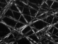 Cross-polarized light
 illumination, sample contrast comes from rotation of
polarized light through the sample.
-
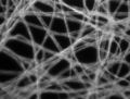 Dark field
 illumination, sample contrast comes from light
scattered by the sample.
-
 Phase contrast
 illumination, sample contrast comes from
interference of different path lengths of light through the sample.
مـآلقيت غير حق المجهر الإلكتروني اما الماسح الضوئي مـآلقيت ..
هذا من ويكيبديا :032: واتمنى انه يفيدك 


